
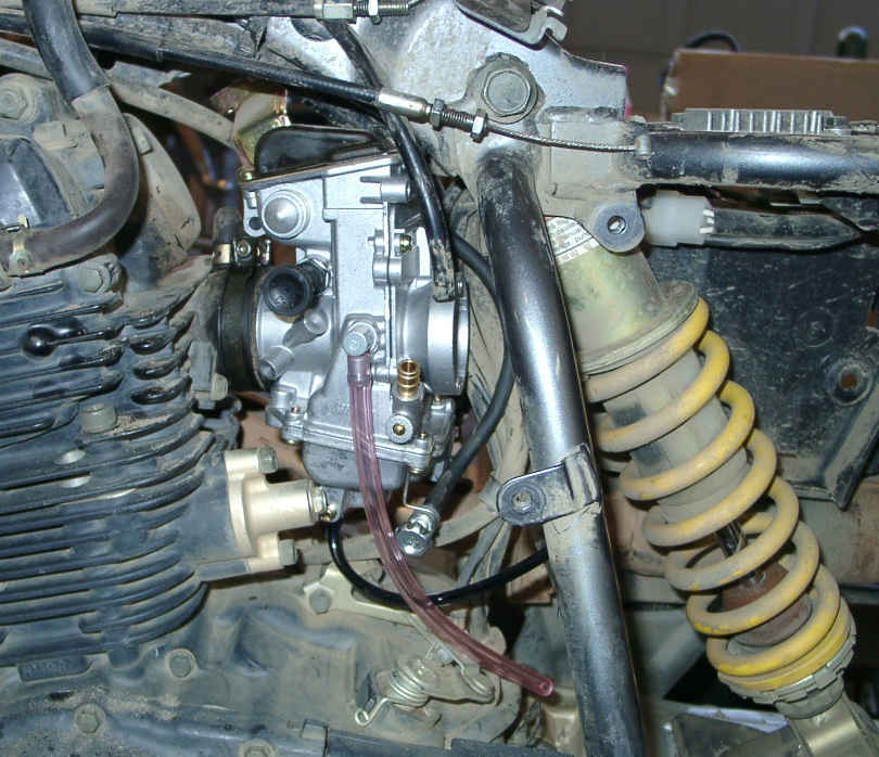
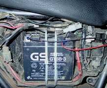
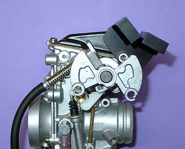
Figure 1 - Stock carb left side
Installing The Mikuni TM33-8012 Pumper Carb:
By Scott Bridgman
|
Update History
|
|
| Created | 1/29/04 |
| Jetting | 3/8/04 |
| Throttle Bracket | 4/6/04 |
| Anodized Parts | 4/28/04 |
| Kit Completed | 6/1/04 |
INTRODUCTION:
My 2003 Yamaha XT225 is a nice bike and for what it was designed for it performs well. At this point I've owned the XT225 for about 7 months and have ridden it approximately 2000 miles most of which has been off road. In my opinion, the bike has performed well under some tough riding conditions and with a few enhancements a great bike can become an excellent bike for the riding I'm presently doing. My goals for this project are as follows:
1) Increase responsiveness to short sudden bursts of open throttle
2) Improve cold starting, reduce warm up time and engine stumble
3) Augment overall engine horsepower and torque
4) Keep the bike quiet
5) Allow the bike to easily be returned to stock condition for resale
To satisfy the above I've selected the Mikuni TM33-8012 carb to replace the stock carb. The model 8012 includes an accelerator pump which should provide an increase in responsiveness as well as improve cold starting. I'm also hoping to reduce the time the engine stumbles during warm up. Even in mild weather the engine can take 10-15 minutes to fully warm up. During warm up the engine is temperamental and will stall when throttle is applied abruptly. Having the engine stumble or worse yet stall while accelerating into traffic is dangerous. This has happened to me on several occasions while road riding and it isn't fun. Finally, having the XT225's engine performance approach that of 250cc 4 stroke dirt bike will make the bike more enjoyable to ride.
Removing The Stock Carb:
In order to evaluate whether the TM33 would install properly I needed to open the bike up and completely remove the stock carb for comparison. Given this project wasn't a direct replacement of an existing part or an upgrade to a known compatible part it wasn't possible to proceed with 100% confidence. In fact I was expecting to encounter an impass that tanked the whole idea of completing this performance enhancement. First I removed the four plastic cowls which exposed the electrical box, gas tank and fuel shut off valve. Next was to remove the seat and disconnect the rubber gas line from the carb at the carb end. Small spring clips exist at the end of the hose which are easy to compress and slide back. I removed the gas tank retainer screw which is clearly visible once the seat is out. With the retainer screw out, remove the tank by pulling it rearward off two large rubber grommets. Lifting the tank up slightly and rocking it side to side while pulling helps ease it out. Clean the pad up under the tank and any other dirt from the center frame tube with a vacuum. This helped me prevent crap from getting in the engine via the inlet port while I was playing around. Next loosen the circular clamp that holds the air box hose onto the inlet of the carb. Remove the breather hose too. Remove all the screws that hold the air box in. They are not all the same length so remember where they came from. The locations of all screws are pretty obvious except the one located behind the battery. Remove the negative terminal and slide the battery out to access this screw. To get the air box out, fold the air box hose towards the battery and pull the air box hose end out first. You may need to fiddle around with this a little but it will come out. Drain any oil out of the breather hose connection. I didn't do this and ended up with a puddle of oil the size of a dinner plate on the floor.
|
|
|
Figure 1 - Stock carb left side
|
Figure 1 shows the bike disassembled as described above. Noting the cramped conditions in and around the carb and given the TM33 is a larger carb wasn't giving me a good feeling at this point. Plus the throttle cables connect on the left side of the stock carb which is opposite to the TM33. The stock carb has a butterfly controlled bore which means the throttle control shaft sits more central to the carb's vertical dimension. This gives more space above for the throttle cables to attach to the carb. On the TM33 the bore is throttled by a slide barrel which places the throttle control shaft higher on it's vertical axis. This proved to be a problem which almost shut the upgrade down. The TM33 is a taller carb and almost no space exists between the stock carb's top and the bikes center frame top rail. At this point things weren't looking so good.
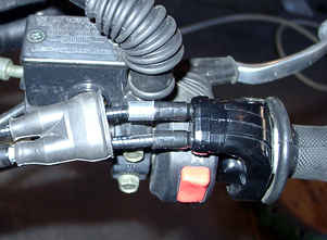
Last step is to remove the throttle cables which requires taking apart the throttle grip on the handle bars. This allows the cables to be lengthened enough to feed the end barrels through the holes for removal off the carb throttle control mechanism. The choke has a disconnect in a black boot just above the cylinder. Pull the black boot back and disconnect the choke cable here. Loosen the ring that crimps the carb at the engine side. Pull the vent hoses up through their strain reliefs and remove the carb by pulling it out of the engine. If the bowl has gas in it keep the carb level to avoid getting a crotch full of high octane fuel as I did. It probably would have been smarter to run the bike out of fuel prior to disassembly. Hind sight is always 20/20.
Carb Comparison:
As mentioned the TM33 is a bigger carb. Its throttle control is higher and opposite to the stock carb. The TM33's choke is a three position pull knob on the left side. Pull for full choke, click in one click for partial choke and push all the way in for no choke. The stock carb uses a remote knob with a cable that runs directly into the carb. The width of the two carbs, as measured from the faces of the bore connections, is essentially the same. The diameters of the bore connections are alos the same.
Installing the TM33 Carb:
I needed to remove the throttle cable retention bracket on the TM33 to reduce its height so it would clear the center frame tube above the engine during installation. Spray the engine rubber inlet port nipple with some WD40 and push the TM33 into position. You'll need to turn the carb slightly and fiddle with it to get it into position but it will go in. Twist the carb into a verical position and snug the inlet port ring just enough to put a little pressure on the connection. You should have about 1/8" of clearance on the back top of the TM33 and the center frame tube. It isn't much but enough to avoid metal to metal contact. Figure 2 shows the TM33 in position.
 |
|
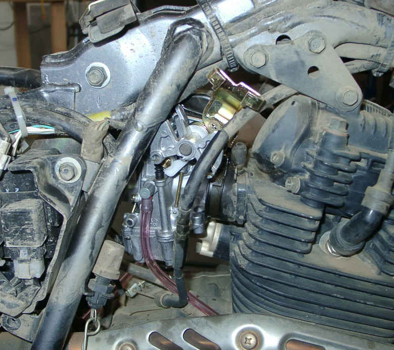
Figure 2 - TM33 carb left side
|
 |
|
Figure 3 - TM33 carb right side
|
 |
|
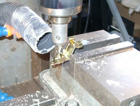
Figure 4 - Cutting Cable Bracket
|
 |
|
Figure 5 -Modified Cable Bracket
|
 |
|
Figure 6 -Air Box Installed w/TM33
|
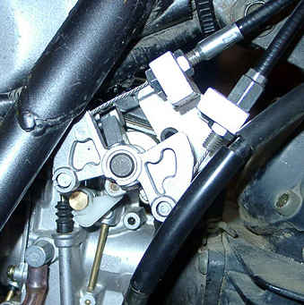
You'll note the drain/vent tubes are all too short but that's an easy problem to solve. Draining fuel away from a hot engine is important so don't forget to retube the vents. I've laid the sled down in the woods on several occasions only to be trapped by the left side. You can't move and you can't turn the fuel off. In this position fuel just pours out of the bike. It may take several minutes before someone arrives to get you out from under the bike. I think you see where I'm headed with this as in if the bike catches fire. Make sure to retube the vents! Now comes the fun part of figuring out how to connect the throttle cables to the TM33. Figure 3 shows the unmodified throttle cable bracket which brings the cables out too high. So high they will hit the gas tank. You'll also see the clutch cable hitting the throttle mechanism. Notice the wiring harness just aboved the throttle mechanism. Everything is very close including the frame tube that runs down off the center frame tube. But there is just enough clearance for the throttle mechanism to operate safely. It's important to make sure the throttle mechanism moves freely to avoid it getting stuck. A stuck throttle in either the open or closed position posses obvious safety risks. Keep in mind the bike uses a two cable system for added safety. The throttle slide barrel opens by the first cable pulling against the TM33's return spring. If friction develops beyond what the return spring can over come the second cable will allow the throttle to be pulled closed by the throttle grip. This is a good design and increases safety but doesn't mean a guaranteed closed throttle if a bad jam occurs. Make sure everything is clear of the throttle mechanism! Remove the bracket that connects the cylinder head to the upper center frame tube. Reroute the clutch and both throttle cables forward of this bracket. Reinstall the bracket. This will clear the clutch cable and allow the throttle cables to come down on the right side of the TM33.
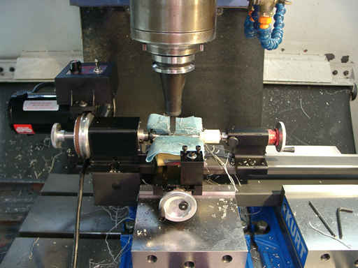
The only problem that remains now is to reduce the height of the throttle cable bracket to avoid the cables from hitting the gas tank. This involves cutting about 1/2" out of the bracket and TIG welding the two pieces back together into one bracket again. I did the cutting on a Bridgeport mill as shown in Figure 4. Cut one separates the bracket into two pieces. A second cut shortens the cable side piece a tad and creates a cross section mitre angle that allows the parts to be mated for TIG welding. A jigsaw can be used to hack out the cuts followed by some grinding to get the parts to fit if you don't have a mill. There is no "home brew" solution to the welding part. They must be TIG welded. Luckily most of the metal is removed from the vertical part meaning you don't disturb the alignment of the cables paying into or out of the throttle mechanism. Bringing the cable about a 1/2" closer to the throttle mechanism did decrease the straight "line of action" of the cables onto and off of the throttle mechanism. This causes the cables to rub slightly more on their termination eyelets. This is so slight you wouldn't notice it and doesn't violate the integrity of the cabling system. One problem you'll need to take care of is the full throttle stop tab on the carb. This will hit the angled part of the cable bracket given it's been lowered. I discovered this after the fact and had to pull the carb out to grind off about an 1/8" from the corner of the stop tab. With the carb out of the bike, install the modified cable bracket and work the throttle by hand. Note where the stop tab hits and mark the offending portion with a pen. Remove the cable bracket from the carb and grind the stop tab down just beyond the pen mark to allow clearance. Reinstall the bracket, check operation and touch up on the grinder as required. After successful operation is achieved, remove the bracket, install the TM33 in the bike and replace the cable bracket. Figure 5 shows the new throttle and clutch cable routing and the modified cable bracket which lowers the cables out of the way of the gas tank. The modified bracket has been sprayed with red primer given the welding destroyed most of the original coating. This bracket is mild steel so there were no issues with the heat affected zone resulting from the welding. A small 1/4" spacer was added to the pull return cable to take up slack. I made the spacer from 3/8" bar stock on a lathe and cut a slot into it on the mill. If a second jam nut was on the adjustment barrel this wouldn't have been necessary. Owing to the original mounting, only a single screw was provided on this cable. The other cable has two screws. Set the adjustments to use maximum cable length on the new bracket. Reassemble the throttle grip and adjust out the slack with the adjustment located on the handle bar near the throttle grip. Operate the throttle from the grip and make sure nothing is hitting the control mechanism at the carb. At this point the tough stuff has been done. Figure 6 shows the carb fully connected and the air box back in the bike. Make sure the carb is in good position and tighten both retainer rings. Check throttle operation again and inspect everything closely before completing the reassembly. Hook up the breather hose to the air box and install the gas tank. The fuel inlet connection on the TM33 is a tad larger than the stock carb but with some WD40 the fuel line hose will fit. The clamp will fit too. It wouldn't hurt to get the vent hoses squared away at this point and exiting down under the bike.
Starting the Bike and Testing:
At this point my bike was completely assembled and ready for a test run. I forgot to completely remove the stock choke control so I need to go back and do that. Its disconnected end is dangling under the gas tank somewhere. I had some thoughts about making an adapter to allow the TM33 to be choked from the OEM knob atop the handlebars. I'm thinking the remote choke is like urinating in a blue suit. It gives you a warm feeling but nobody notices. Since the TM33 side mount choke is easy to get at I don't think this is really worth the effort. You can easily reach under the cowl and pull the choke lever once you know it's there. This hidden choke knob might be a good anti theft device. Temps outside the shop were around 25 degrees when I rolled the TM33 equipped bike outside to start it for the first time. I turned the fuel on, pulled the choke out and pressed the start button. Just 2 cranks and she started right up and purred at fast idle. Not really a good cold start test given the bike was at room temperature when I started it. I was just glad to hear the bike fire up. And fire up it did. Unlike the stock carb you don't need as much choke so after several minutes I started to cut back on the choke. After about 5 minutes I killed the choke all together and set the idle speed. After reving the engine a few times I knew this upgrade was worth the effort. With raw fuel squirting into the intake the acceleration was strong and confident. A short test ride confirmed this. The bike performed significantly better with this carb installed with an apparent widening of the power band. I'd say a 10-20 percent increase in acceleration and power at the low end is what you'll get IMHO. The bike runs rich at mid to WOT so some rejetting will be required to get the carb tuned for proper operation over the entire throttle range. A dynamometer would reveal exact power and torque increases but to be honest that information doesn't really matter a whole lot to me. Part of what makes riding a bike fun is being able to roll the throttle on and feel the best performance your engine size can deliver. Iffy acceleration and engine stumble just doesn't cut it. The TM33 carb eliminates these negative performance factors. I don't mean using extra power like a maniac I mean knowing you have the best most reliable power available to accomplish your purpose. For me that purpose means more power to merge with traffic on the road. Off road it means a quick blast of throttle reliably brings the front wheel up to clear logs, rocks or roll off ledges. Whatever type of riding you're doing I can't imagine any XT225 owner being disappointed with this upgrade. Finally, nothing has been altered on the bike that can't be put back if you plan on reselling the bike and want to offer it completely stock. I've saved my stock carb just for that purpose. It's stored back in the TM33 box.
Re-Jetting The TM33:
As many people already know jetting and tuning a carb for specific engine is a black art which is another way of saying trial and error. Anyone undertaking this process better be patient and plan on many cycles of disassembling the carb, tweaking it and reassembling it. Some of the tweaking can be done with the carb on the bike while most of it requires removing the carb completely to change out jets, needles and throttle slides. It took me over 25 tweaking cycles to get the carb close to where it is ready for final tuning. I searched high and low for some guide lines to establish a close jetting for an engine size of around 250cc. The XT225 engine is actually 223cc discplacement. You might think that Mikuni would publish this data for the TM33 carb but no suck luck. You might think those selling this carb would have some suggestions about jetting and engine size but think again. The only statement about jetting I was able to pry out of someone was, "It should run a little on the rich side." Looking through the tuning manual reveals the carb to be jetted smack in the middle of the available ranges allowing the carb to be made richer or leaner to the same degree on either side. Not much help. To solve the jetting riddle I decided to examine the OEM carb for clues to explain the apparent mixture deviations on the TM33 carb which might suggest which direction (bigger or smaller) to go to. The specs for my USA (none California) 2003 XT225 are below:
|
2003 XT225 Mikuni BST34 Carb Specs
(ID Mark 4BEV 30) |
|
| Main Jet |
#125 (1.25mm) |
| Main Air Jet | 1.0 |
| Jet Needle | 5DL27-1 |
| Needle Jet | 0-1 |
| Pilot Air Jet 1 | #70 |
| Pilot Air Jet 2 | #1.2 |
| Pilot Outlet | 0.85 |
| Pilot Jet | #40 |
| Bypass 1 | 0.8 |
| Valve Seat Size | 2.0 |
| Starter Jet 1 | #65 |
| Starter Jet 2 | 0.8 |
| Throttle Valve Size | #130 |
| Fuel Level | 11.5mm |
Keep in mind the bike was thought to be running rich from about mid throttle to WOT off of the default jetted TM33. The items highlighted in red were of particular interest given they have a dominate contol over the mixture from 1/4 throttle to WOT. These parts also have direct cross reference to the TM33. The BST34 is a CV carb with a coaster enrichment system hence it has more pilot jets, a bypass and a few other passages that are associated with the vacuum slider control mechanism.
 |
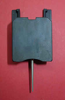
|
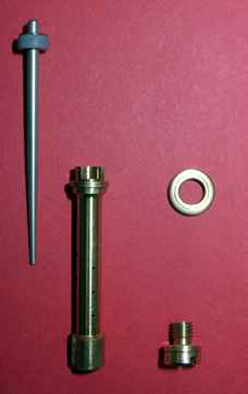
Figure 7-OEM Carb Needle Set
|
These extra parts don't exist on the TM33. Figure 7 shows the OEM carb's needle
set which includes the jet needle (left), needle jet (center) and main jet with
washer (right). The needle measures 2.50mm towards the top which doesn't start
to taper until about 1/3 the way down. Note a single e-ring position and a plastic
spacer which moves the needle towards a richer postion. The inside diameter
of the needle jet is 2.60mm leaving a difference of .10mm in diameters. Note
the needle jet is of a bleeder design owing to the 10 holes drilled along its
length. Using an optical comparitor these holes measured 0.7mm each for a total
area of 15.44 square mm. Bleeder needles pre-mix air with fuel prior to it entering
the bore. This helps atomize the fuel into tiny droplets. Air is drawn in through
the main air jet for this purpose. Of particular interest is the small slotted
cup at the top of the needle. The slot faces the engine and assists the venturi
action which helps direct fuel towards the engine. Once the pre-mixed fuel enters
the bore it is again mixed with more air which should achieve a final mix ratio
of about 14.7:1 and create optimal burning in the engine. Visual inspection
of the TM33 carb during bursts of throttle revealed excessive splashing of fuel
out of the carb away from the engine. The TM33's needle jet doesn't have a slotted
cup. My guess is Mikuni made some design improvements in the way fuel atomizes
on the OEM carb by using a slotted cup style needle jet. The TM33 needle jet
is also a bleeder style with 10 total holes of 0.63mm, 0.7mm and 1.0mm totalling
an area of 24.42 square mm. The TM33 needle jet measures 2.69mm with the jet
needle measuring 2.54mm creating a difference of 0.15mm in diameters. This allows
more fuel to enter which could explain the rich mixture but the bleeder hole
area is also greater tending to lean the mixture. The lack of a slotted cup
on the TM33 and a different throttle slide cut influence the venturi action.
Like I said this is a black art. Still convinced the bike was running rich,
based on advanced methods like smelling the exhaust, I decided to machine a
new needle jet to fit the TM33. I replicated the OEM bleeder hole size with
the TM33 drilling position , inside diameter of 2.60mm and created a slotted
cup. Using this new needle jet with the 5 series jet needle supplied with the
TM33 carb made a world of difference but still wasn't 100%. The main air jet
was left alone. That solved most of the rich mixture problems and greatly improved
the high end performance. The last issue is to correct a small chunky running
condition at 1/8 throttle and bring the fuel delivery to 100%. The slide cut
away transistions the fuel mixture from 0 throttle to 1/4 throttle. The TM33
throttle slide cut is believed to be too small now that the slotted cup is in
the bore. Plans are to machine that open in small increments of about 1mm and
see what happens. A new jet needle will need to be created too.
 |
|
Figure 8-TM33 Throttle Slide
|
 |
|
Figure 9- OEM Throttle Slide
|
 |
|
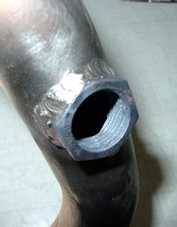
Figure 10- O2 Sensor Fitting in Exhaust
Pipe
|
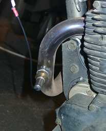 |
|
Figure 11- O2 Sensor on XT225
|
 |
|
Figure 12- Deriving Power off Battery
|
 |
|
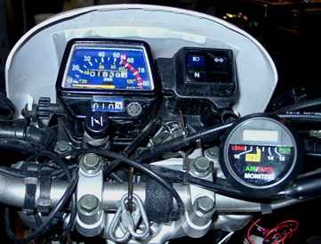
Figure 13- A/F Meter Wedged Between
Throttle Cables
|
 |
|
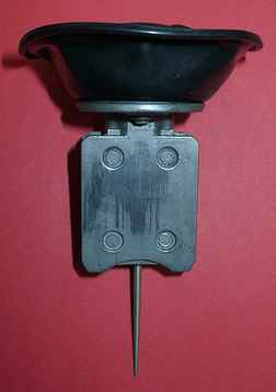
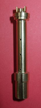
Figure 15 - Prototype Needle Jet for
TM33 Made by Hand
|
Figures 8 and 9 show the two throttle slides and the differences in their cuts. As the throttle is moved to 1/8 position the slide begins to raise which increases the velocity of air through the bore and starts the venturi action. At this point the needle jet by virtue of venturi action begins to feed fuel into the bore moving the fuel feed off the pilot system onto the needle jet. Actually the pilot system is still feeding fuel but in small proportion to the needle jet. The slide cut out influences the air currents over the needle jet. Execessive air turbulence here can cause irratic fuel feed. This isn't an exact science by any stretch of the imagination so experimentation is required to see what happens. After cutting another 1.4mm from the throttle slide the mixture was way too lean. This didn't solve the 1/8 throttle mixture problem as expected. The slot might need to be made smaller which is a more difficult fabrication process. Or the needle might need to taper toward a smaller size faster as it comes out of the needle jet.
A/F Meter Reading:
I'm at the point now where the TM33 carb is very close to correct operation. I now have the A/F meter which will allow me to analyze the performance of the TM33 carb. First step is to get a baseline from a stock XT225. Figure 10 shows the installation of the O2 sensor fitting which must be welded into the exhaust pipe. With the fitting welded in, the O2 sensor is easily screwed in as shown in Figure 11. The meter uses 12 volts so I jacked into the battery box as shown in Figure 12. The meter is wedged in between the throttle cables as shown in Figure 13 for reading under actual driving conditions. A characteristic of O2 sensors is they are non linear with a steep curve right around the 0.45 volt mark which is the correct combustion mixture of 14.7:1. This causes the voltage (and LED display segments) to dance up and down rapidly. The O2 sensor provides very rapid response in the order of 10's of milliseconds. This will sense slight (and normal) variations in combustion which is never perfect. The first readings were taken on the stock serow for a base line. As expected the bike runs rich during warm up with enricher on then settles in for a proper mixture over the entire throttle band. My K&N setup reads just a tad on the rich side but I don't think that means anything. After changing front pipes I took readings on the TM33 equipped serow which are tabulated below:
|
A/F Comparison
|
||
| Throttle Position |
Stock Bike
|
TM33 Bike
|
|
0 (Warm Up)
|
Very Rich
|
Very Rich
|
|
0 (idle)
|
Good+
|
Rich
|
|
1/8
|
Good+
|
Very Lean
|
|
1/4
|
Good+
|
Lean
|
|
1/2
|
Good+
|
Lean
|
|
3/4
|
Good+
|
Lean
|
|
WOT
|
Good+
|
-Lean
|
The above readings tell me the needle jet and jet needle taper are close to correct. I may need to move the needle up a notch to richen the mixture from 1/4 to 3/4 throttle. Like every other tuning adjustment I'll take the carb down, make the adjustments and see what happens. The low speed rich condition is the pilot system which is easy to correct with the mixture screw and/or pilot jet. First order of business is to get the pilot system correct. The very lean condition at 1/8 throttle I now believe to be the slide cut out being too large. The WOT throttle might be okay with the jet needle moved up or I may need a larger main jet. At this point I'm look for things I can change that create improvements. After working the pilot system I'll do the easy jet needle adjustment as required. Fuel feed circuits aren't completely isolated so working from the bottom up is best. After play with the carb some more it turns out the bike runs well with the jet needle in the rich position. This doesn't leave any more adjustment on the rich side. Getting that last little bit of balance and correct fuel delivery will require a deeper analysis.
Establishing Baseline Jetting:
It is my feeling a good amount of time was devoted by Yamaha in setting up the BST34 CV carb to provide good overall performance. I've disected the OEM carb with emphasis on the needle jet and jet needle. Scaled drawings of the needle jet and jet needle were created based on measurements, common sense and investigations. This general information appears in Figure 14 below:
 |
|
Figure 14 - Fuel Delivery Analysis
|
The needle jet and jet needle are shown in proper position for the carb when the engine is at idle (0 throttle). The colored bars show the orifice position as the needle is pulled from the needle jet when the throttle is advanced. This information allows me to see how the needle and needle jet work together to deliver fuel at key throttle positions. Keep in mind all of this science becomes only a guideline to get the fuel delivery "close" or within tuning range of what the engine likes. Fuel delivery, atomizing, turbulence and a host of other physical principles defy an exact analysis. The BST34 carb's theoretical air velocity should be slightly slower given its bore is 1mm larger. But the volume subtracted by the butterfly value and control shaft might make its effective bore smaller than 33mm. These restrictions don't exist in the venturi area of the carb where fuel is drawn in. Down stream, the air disturbances introduced by the shaft and butterfly valve may also help atomize the air fuel mixture. This is what makes carb tuning to a specific engine an empirical process with many failed attempts. Owing to a different design of the two throttle slides it isn't possible to experiment with the OEM needle in the TM33. It's too short. However, its relative fuel delivery properties do transfer once the length differences are resolved. In addition to a new needle jet a jet needle was also created. Figure 15 shows the prototype needle jet I machined (1 off by hand) to fit the TM33 carb. A needle jet with these properties isn't available for the TM33. Same situation applies for the jet needle. These prototype parts will serve as the basis for the production versions. I may add two additional e-ring positions to the jet needle to allow an additional rich and lean setting to help resolve temperature and altitude variations. This could also be handled by adjusting the overall jet needle's diameter. Both the needle jet and jet needle work together as a pair so having precise control over their dimensions allows complete flexibility in design. This is a big plus for parts that must be tuned or tweaked. As mentioned it's been a fun time.
Making Production Parts:
After establishing what works in a single carb via prototype parts the next step is to promote the physical properties of these prototype parts into a short run (about 20 sets) production fabrication scheme. For critical dimensions like the needle jet orifice and jet needle diameter, absolute and repeatable accuracy is very important and must be held to within +-.0001". This will ensure that combinations of these parts will function consistently in the field and eliminate hand testing and pairing. Other physical dimensions like bleeder holes and jet needle length don't need to be held this close. Carburetors are very crude devices and nothing makes them perfect that's why closed loop computer controlled fuel injection will most likely be what you will see more and more on small I/C engines. With that said you do the best you can to achieve proper performance.
 |
|
Figure 16 - Production Needle Jet
Set in Partially Finished State
|
By far and away the biggest challenge was to deal with the turning issues
associated with the jet needle. Figure 16 shows this part (bottom of frame)
just after the taper has been cut into the aluminum rod. Parting the needle
off and adding in the e-ring slots are a comparitive vacation. Because this
part is both thin (.046" at small end) and long special fixturing is
required to turn it accurately. In contrast the brass needle jet is a relatively
easy part to turn in any CNC lathe. The brass part is shown as a solid turning
and requires a slot, main jet screw thread, cup cut, center drill, bleeder
holes and orifice boring to complete it. The orifice boring is the most
exacting of these machining operations and will be handled by a miniature
carbide boring tool hand ground for the small hole required. Figure 17 shows
a somewhat unorthidox way of turning a long skinny precision part. Using
the small lathe to turn the stock the CNC mill can cut in the X-Z plane
while holding Y constant. This allows the correct profile to be put on the
needle. Calling in a grooving tool will handle cutting the e-ring slots
and place them precisely with the needle taper. Parting off the needle isn't
critical and can be done as a post op.
 |
|
Figure 17 - Production Jet NeedleTurning
Handled by a Special Fixturing Setup in CNC Milling Center
|
 |
|
Figure 18 - Solid Turning of Production
Needle Jets Completed
|
 |
|
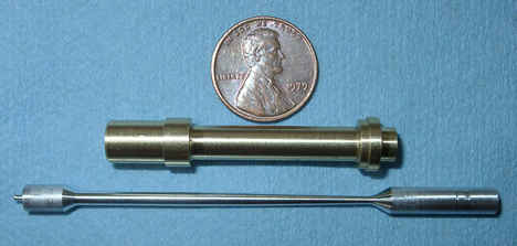
Figure 19 - Production Jet Needle
(left) and Needle Jet.
|
 |
|
Figure 20- Completed Throttle Cable
Bracket.
|
 |
|
Figure 21- Throttle Off Cable Spacer
(silver barrel in top cable).
|
 |
|
Figure 22 - Throttle Cable Bracket
(left) and Spacer (right).
|
 |
|
Figure 23 - Anodized Throttle Cable
Bracket on TM33.
|
 |
|
Figure 24 - Anodized Throttle Cable
Bracket, Spacer & Screw.
|
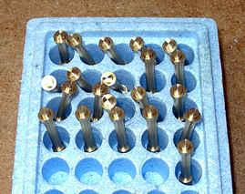
The next challenge is to complete the machining on all the brass needle jets then test these with the production jet needles and adjust the taper and e-ring positions as required. If all goes well this will yield parts that will deliver consistent results and allow altitude and temperature adjustments via the e-ring position. Figure 18 shows the batch of 20 brass needle jets right after CNC lathe turning. They await completion.
I'm a big fan of Murphy. He said, "If all goes well you've over looked something." Remember Murphy was an optimist! I'll be adding updates as progress is made.
Finishing Production Jetting:
Several weeks have passed since Figures 16, 17 and 18 were taken. In that time I've completed all the machining and orifice drilling on the jetting parts required to tune the TM33 to the XT225 engine. The jet needle was the most challenging part to produce. Extra effort was expended here to allow complete in house control of the needle's profile which make quick adjustments in the profile to suit the engine possible. To machine needles, the setup shown in Figure 17 has remained basically the same with the addition of a more rigid tail stock and a linear compensation to account for stock deflection during turning. Needles where machined, installed in the carb then evaluated during a test ride. Small adjustments were made until the mixture satisfied the proper air/fuel ratio over the needle's control range. It was a requirement for the needle to provide proper performance here when set to the middle ring. This allows two positions rich and lean for local jetting adjustments if they are required. The last change that was made to create a working needle was to shift the e-ring group up .5mm. Figure 19 shows the production needle jet and jet needle. To complete the needle jet (right) center drilling was done, the cup cut was milled, bleeder holes drilled, registration slot cut, main jet threads added and finally the orifice hole was drilled in last. The production needle jet was derived from the prototype part shown in Figure 15 above. The base line jet needle profile was taken from the stock carb's needle then tweaked to work properly. A special tool was ground from a high speed steel blank to cut the .45mm e-ring slots.
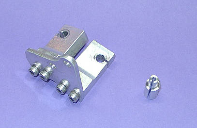
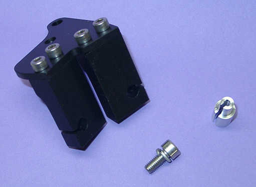
Throttle Cable Bracket:
The last set of fabricated items to be completed for this kit are the throttle bracket parts. The goal is to allow easy assembly without cutting any of the stock cables. Being able to use the stock cables unmodified with the TM33 pumper carb means you can revert back to the OEM carb should that be necessary for any reason. Aside from using the stock lengths, several other challenges had to be met. First - the new bracket needed to be low in height profile to prevent cables exiting the bell crank from hitting the gas tank. (It was this problem that led to scrapping the TM33's original bracket.) Second - tangential cable pulling angles needed to be restored at this lower height. Third - existing mountings both carb side and cable ends needed to be matched. Forth - a throttle stop needed to be created to limit WOT. Figure 20 shows the new bracket design implemented from aluminum. It consists of a flat mounting plate attached to the TM33's mounting boss with two perpendicular protruding blocks that hold the cables securely above the bell crank. Notice the blocks are set for proper "pull off" angles to prevent rubbing of the cable as it runs in and out of the sheath. Several trial brackets where made to tune all of the angles and dimensions so the fit was correct. Because of the lower height of this new bracket extra cable was produced on the "throttle off" cable. Some extra cable was also produced on the "throttle on" cable but to a much smaller extent. Two places exsist in the "throttle on" cable to take up slack and these adjustments where run out slightly to take up slack and still preserve an adjustment range. A split spacer was made and installed in the "throttle off" cable as shown in Figure 21. No explicit adjustment exists in the "throttle off" cable. Luckily the sleeves that conduct the cables into the throttle grip are molded polypropylene and only crimped onto the cable sheaths. Using a heat gun or hair dryer the "throttle off" cable sleeve was heated and easily slid off the sheath. The aluminum spacer was pressed into the sleeve and the cable sheath slides into it effectively taking up the required slack of about 10mm. The water boot covers the spacer and small slot required to get it over the cable so the finished assembly remains water tight. Figure 22 shows the throttle cable bracket and spacer. Four SS socket head cap screws hold the cable supports to the flat mounting plate. The original flat head cable bracket mounting screw was replaced with a 5mm x 12mm cap screw. After removing part of the tang on the bell crank the mounting screw's head serves as the throttle stop. Somehow it was in perfect position. Examine Figure 20 again and you will see this cap screw partially hidden by the right side of the bell crank. Take notice of the bell crank's throttle stop tang which will hit this screw. The original bracket had a bent tab which functioned as the limit stop. If older XT225s are set up as my 2003 bike is with the polypropylene sleeves the spacer will work fine. Note cables connect to the TM33 carb on its right side which is opposite to the OEM carb. Enough length exists to facilitate this rerouting without undue cable pull or tension. Production parts will be sent out for black anoziding. The parts shown are the final design and currently installed on my bike for testing. The new bracket has seen about 6 hours of woods riding with no problems.
Figure 23 shows the completed throttle cable bracket, after anodizing, installed on the TM33. A single SS socket head cap screw is used to hold the bracket in place and provide the WOT stop. Cables can now be brought in close to the bell crank to avoid interference with the gas tank. The support blocks are modular allowing one to be removed for older bikes with a single pull cable. The TM33 has a strong return spring to move the throttle to the closed position. Newer bikes went to the safer push/pull system. Figure 24 shows a close up of the anodized throttle bracket parts, cable spacer and SS mounting screw with lock washer. 4 socket head cap screws securely hold the cable blocks to the mounting plate. 20 sets have been produced. The cable bracket has seen about 30 hours of use at this point with no mechanical problems.
Kit Completed:
I experienced some problems with producing needles with repeatable accuracy. This required a change to the turning fixture shown in Figure 17. The new fixturing corrected this problem and now the computer model's needle profile matches that of the machined part. Copies can now be made within tolerance. The kit has been tested for some 500 miles both on the road and in the woods with pleasing results. Kits can now be purchased from my online store. If anyone has questions, concerns or comments about this project or the kit please feel to contact me at anytime.